
Mounting Instructions (Set-Screw)
1. Inspect the Shaft
- Measure the shaft to ensure it is within recommended tolerances per Table 1
- Check for any nicks or burrs that might prevent the bearing from sliding on the shaft easily
- Clean the mounting surface, then apply a film of light weight oil
2. Place the Bearing on the Shaft
- Do not hammer the bearing onto the shaft
3. Bolt the Housing to the Mounting Surface
- The bearing and shaft must be aligned within 2°
- Rotate the shaft to ensure it rotates smooth and freely
- It is expected that plain washers will be used under mounting bolt heads to span the slot width
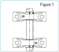
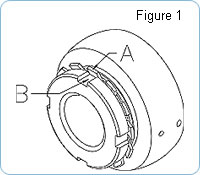
4. Align the Set-Screws of the Bearings at Both Ends of Shaft
- See Figure 1
5. Alternate tightening of Set-Screws
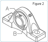
- Tighten set-screw “A” half of the recommended tightening torque (Figure 2)
- Tighten set-screw “B” all the way to the recommended tightening torque (Figure 2) per Table 2
- Go back to set-screw “A” and tighten it all the way to the recommended tightening torque with a variable torque wrench per Table 2
Recommended Shaft Tolerances:
| Inch Size Shafting | Metric Size Shafting |
|---|---|
| Shaft Diameter up to 1-15/16″ Nominal to – 0.0005″ |
Shaft Diameter up to 45 mm Nominal to – 0.013 mm |
| Shaft Diameters 2″ to 4-7/16″ Nominal to – 0.0010″ |
Shaft Diameters 50 mm to 140 mm Nominal to – 0.025 mm |
Recommended Tightening Torque of Set-Screws:
| Applicable Inch Bearing No. for Corrosion Protection Bearings | Recommended Max. Set Screw Tightening Torque (in-lbf) | |||
|---|---|---|---|---|
| zone hardened inner ring | through hardened inner ring | |||
| B1-8MZ2~B2-10MZ2 | 21 | |||
| B4-12MZ2 | 22 | |||
| UC201-8MZ2~UC202-10MZ2 | MUC201-8~MUC206-20 | 35 | ||
| UC204-12MZ2~UC206-20MZ2 | B5-16MZ2~B6-20MZ2 | 43 | ||
| MUC207-20~MUC209-28 | 74 | |||
| UC207-20MZ2~UC209-28MZ2 | B7-20MZ2~B8-24MZ2 | 104 | ||
| MUC210-30~MUC213-40 | 143 | |||
| UC210-30MZ2~UC211-35MZ2 | 208 | |||
| Applicable Metric Bearing No. for Corrosion Protection Bearings | Recommended Max. Set Screw Tightening Torque (in-lbf) | |
|---|---|---|
| zone hardened inner ring | through hardened inner ring | |
| B4MZ2 | 22 | |
| UC202MZ2~UC203MZ2 | 35 | |
| UC204MZ2~UC206MZ2 B5MZ2~B6MZ2 |
43 | |
| UC207MZ2~UC209MZ2 | 104 | |
| UC210MZ2 | 208 | |
| MUC201~MUC206 | 21 | |
| MUC207 | 35 | |
| MUC208 | ||
| MUC209 | ||
| MUC210~MUC211 | 74 | |
| MUC212~MUC213 | 143 | |
| MB4 | 21 | |
| MB5~MB6 | ||
| MB7 | 35 | |
| MB8 | ||
| Applicable Inch / Metric Bearing No. for Mounted Bearing Units | Recommended Max. Set Screw Tightening Torque (in-lbf) | ||||
|---|---|---|---|---|---|
| zone hardened inner ring | through hardened inner ring | ||||
| B1~B3 | 21 | ||||
| B4 | 22 | ||||
| UC201~UC203 | UC305~UC306 | UCX05 | 35 | ||
| UC204~UC206 | B5~B6 | 43 | |||
| UC307 | UCX06~UCX08 | 74 | |||
| UC207~UC209 | B7~B8 | 104 | |||
| UC308~UC309 | UCX09~UCX12 | 143 | |||
| UC210~UC213 | 208 | ||||
| UC214~UC216 | 347 | ||||
| UC217~UC218 | UC310~UC316 | UCX13~UCX18 | 247 | ||
| UC317~UC324 | UCX20 | 590 | |||
| UC326~UC328 | 998 | ||||
Mounting Instructions (Eccentric Locking Collar)
1. Inspect the Shaft
- Measure the shaft to ensure it is within recommended tolerances per Table 1
- Check for any nicks or burrs that might prevent the bearing from sliding on the shaft easily
- Clean the mounting surface, then apply a film of light weight oil
2. Place the Bearing on the Shaft
- Do not hammer the bearing onto the shaft
3. Bolt the Housing to the Mounting Surface
- The bearing and shaft must be aligned within 2°
- Rotate the shaft to ensure it rotates smooth and freely
- It is expected that plain washers will be used under mounting bolt heads to span the slot width
4. Fasten the Unit to the Shaft
- Place the eccentric locking collar on the track of the inner bearing ring
- Rotate the collar by hand in the direction of rotation until the eccentric cam is engaged
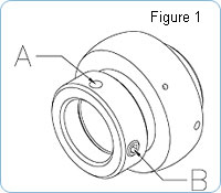
- Insert a drift pin or straight punch in the hole on the O.D. of the collar “A” and strike with a small hammer to positively engage the collar
- Tighten the set screw “B” to the recommended tightening torque per Table 2 to hold the collar in the engaged position
Recommended Tightening Torque of Set-Screw in Eccentric Locking Collar:
| Applicable Bearing # | Recommended Max. Set Screw Tightening Torque (in-lbf) | ||
|---|---|---|---|
| UG204-UG205 | KH201-KH205 | KHR201-KHR205 | 43 |
| UG206 | KH206 | KHR206 | 104 |
| UG207-UG210 | KH207-KH210 | KHR207-KHR210 | 208 |
| UG211-UG212 | KH211 | KHR211 | 234 |
Mounting Instructions (Accu-Loc®)
1. Inspect the Shaft
- Measure the shaft to ensure it is within recommended tolerances per Table 1
- Check for any nicks or burrs that might prevent the bearing from sliding on the shaft easily
- Clean the mounting surface, then apply a film of light weight oil
2. Place the Bearing on the Shaft
- Do not hammer the bearing onto the shaft
3. Bolt the Housing to the Mounting Surface
- The bearing and shaft must be aligned within 2°
- Rotate the shaft to ensure it rotates smooth and freely
- It is expected that plain washers will be used under mounting bolt heads to span the slot width
4. Fasten the Unit to the Shaft
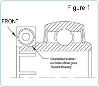
- Place the locking collar on the tangs of the inner bearing ring with the chamfered corner on the bore of the collar toward the bearing. The collar is stamped with the word “FRONT” this should be facing away from the bearing and readable to the installer.
- Tighten the capscrew to the recommended tightening torque per Table 2 using a variable torque wrench
Recommended Tightening Torque of Accu-Loc Collar Capscrews:
| Applicable Inch Bearing No. | Recommended Max. Set Screw Tightening Torque (in-lbf) | |
|---|---|---|
| Black Oxide Finish | Kanigen Corrosion Protection (MZ20 Type) | |
| UE204-12 – UE206-20 | 60 | 30 |
| UE207-20 – UE208-24 | 90 | 45 |
| UE209-27 – UE209-28 | 90 | 40 |
| UE210-31 – UE211-32 | 140 | 90 |
| UE212-39 | 250 | 160 |
| UEX05-16 | 35 | – |
| UEX06-19 – UEX09-28 | 70 | – |
| UEX10-31 – UEX11-35 | 140 | – |
| Applicable Metric Bearing No. | Recommended Max. Set Screw Tightening Torque (in-lbf) | |
|---|---|---|
| Black Oxide Finish | Kanigen Corrosion Protection (MZ20 Type) | |
| UE204 – UE206 | 35 | – |
| UE207 – UE209 | 70 | – |
| UE210 – UE211 | 140 | – |
| UE212 | 250 | – |
Mounting Instructions (Adapter Sleeve)
Bearing units with adapter sleeves permit wider shaft tolerances and can be used in applications where vibration and shock is heavy, as this locking device has superior holding power over all other types.
1. Inspect the Shaft
- Measure the shaft to ensure it is within recommended tolerances per Table 1
- Check for any nicks or burrs that might prevent the bearing from sliding on the shaft easily
- Clean the mounting surface, then apply a film of light weight oil
2. Mount the Adapter Sleeve
- Slide the adapter sleeve onto the shaft with the threads on the sleeve facing the outboard side
- Position the sleeve at the approximate location of the bearing centerline
3. Mount the Bearing
- Apply a light coating of oil on the outside diameter of the sleeve and threads
- Starting with the large end of the bearing bore, slide the bearing onto the adapter sleeve so that the taper of the bearing matches the taper of the sleeve
4. Bolt the Housing to the Mounting Surface
- The bearing and shaft must be aligned within 2°
- Rotate the shaft to ensure it rotates smooth and freely
- It is expected that plain washers will be used under mounting bolt heads to span the slot width
5. Install the Locknut and Lockwasher
- Slide the lockwasher on the adapter sleeve with the inner prong of the lockwasher pointing toward the bearing
- Install the locknut on the threads of the adapter sleeve with the chamfered face toward the bearing
- Tighten the locknut using a spanner wrench to the recommend torque specifications per Table 2
- Find a lockwasher tang “A” nearest to one of the slots “B” in the locknut. If a slot does not line up with one of the tangs on the lockwasher, back off the locknut until one does
- Bend the tang of the lockwasher into the slot of the locknut. This will retain the correct position of the locknut
Recommended Tightening Torque of Adapter Sleeve Locknut:
| Applicable Bearing # (Normal Duty) |
Normal Load Application (ft-lbs) | Heavy Load Application (ft-lbs) | ||
|---|---|---|---|---|
| min | max | min | max | |
| UK205 | 11 | 22 | 14 | 29 |
| UK206 | 14 | 29 | 22 | 43 |
| UK207 | 22 | 43 | 36 | 72 |
| UK208 | 29 | 58 | 43 | 87 |
| UK209 | 29 | 58 | 43 | 87 |
| UK210 | 36 | 72 | 54 | 108 |
| UK211 | 51 | 101 | 76 | 152 |
| UK212 | 72 | 145 | 105 | 210 |
| UK213 | 80 | 159 | 119 | 239 |
| UK215 | 94 | 188 | 134 | 268 |
| UK216 | 116 | 231 | 170 | 340 |
| UK217 | 148 | 297 | 217 | 434 |
| UK218 | 177 | 354 | 260 | 521 |
| Applicable Bearing # (Medium Duty) |
min | max | min | max |
| UKX05 | 14 | 29 | 25 | 51 |
| UKX06 | 25 | 51 | 36 | 72 |
| UKX07 | 29 | 58 | 43 | 87 |
| UKX08 | 36 | 72 | 54 | 108 |
| UKX09 | 43 | 87 | 65 | 130 |
| UKX10 | 58 | 116 | 87 | 174 |
| UKX11 | 76 | 152 | 112 | 224 |
| UKX12 | 87 | 174 | 130 | 260 |
| UKX13 | 119 | 239 | 174 | 347 |
| UKX15 | 141 | 282 | 203 | 405 |
| UKX16 | 166 | 333 | 246 | 492 |
| UKX17 | 203 | 405 | 304 | 608 |
| UKX18 | 231 | 463 | 347 | 694 |
| UKX20 | 333 | 665 | 492 | 984 |
| Applicable Bearing # (Heavy Duty) |
min | max | min | max |
| UK305 | 14 | 29 | 22 | 43 |
| UK306 | 22 | 43 | 33 | 65 |
| UK307 | 29 | 58 | 43 | 87 |
| UK308 | 40 | 80 | 58 | 116 |
| UK309 | 54 | 108 | 80 | 159 |
| UK310 | 72 | 145 | 112 | 224 |
| UK311 | 90 | 181 | 130 | 260 |
| UK312 | 112 | 224 | 166 | 333 |
| UK313 | 130 | 260 | 195 | 391 |
| UK315 | 184 | 369 | 260 | 521 |
| UK316 | 217 | 434 | 325 | 651 |
| UK317 | 260 | 521 | 383 | 767 |
| UK318 | 297 | 593 | 448 | 897 |
| UK319 | 347 | 694 | 521 | 1042 |
| UK320 | 434 | 868 | 600 | 1201 |
| UK322 | 448 | 897 | 890 | 1779 |
| UK324 | 593 | 1186 | 1049 | 2098 |
| UK326 | 723 | 1447 | 1302 | 2604 |
| UK328 | 1049 | 2098 | 1555 | 3110 |
NOTE: Heavy load application is when the radial load is greater than 30% of the bearings dynamic load capacity.